TVT and TST projection modes
About TVT and TST projection modes
In addition to the three standard projection modes, MD, TVD and TVDSS, the Well View also includes the True Vertical Thickness (TVT) and True Stratigraphic Thickness (TST) projection modes. With these features you can visualize:
- missing wellbore sections, for example due to normal faulting or the presence of an unconformity.
- overlapping wellbore sections (via multiple tracks display) due for example to reverse faulting or the presence of inflection points.
- depositional thickness variations without bias as a result of wellbore deviation and/or dipping formations.
Displaying missing and/or overlapping sections can be done in TVT or TST projection modes. An overlapping section that is the result of an inflection point can also be displayed in TVD or TVDSS modes, but only when the inflection point is caused by the wellbore trajectory becoming shallower (i.e. decreasing TVDSS).
Use the TVT or TST projection mode when you are correlating wells in dipping formations. To see more on how to observe depositional thickness variations in a geologically meaningful way, see the section Setting datum with TVT/TST projection.
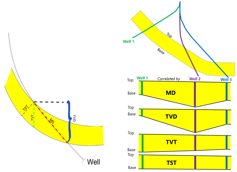
For a dipping formation, the thickness differs depending on the selected projection mode. click to enlarge
Before you can display missing or overlapping wellbore sections you will first need to perform a number of operations in the TVT/TST button group of the Prepare > Wells sub-strip to generate the required data. These operations include the calculation of dip and azimuth from a structural model, seismic interpretation, surface set or 3D grid, the creation of a TVT/TST projection from the dip and azimuth data, and (if you want to calculate inflection points) the generation of inflection points based on a TVT/TST projection.
The dip, azimuth and fault offset data required to make use of these features can all be imported via the standard Logs import processes in the Data strip.
Displaying projection data in the Well View
After you have created the requisite data described above, you can properly display gaps in sections (due to a normal fault or an unconformity) or overlapping sections (due to a reverse fault or inflection point). Follow the steps below to apply a TVT/TST projection to the Well View:
- Check the box for the marker set, wells, and logs of interest in the JewelExplorer so that they are displayed in the Well View.
- Select the TVT or TST projection depth in the Measure drop-down list at the top of the Well View.
- In the adjacent drop-down list select the TVT/TST projection
Gaps in wellbore sections
A gap in a wellbore section is represented by a blank interval in the track at the point where the wellbore intersects for example a normal fault or unconformity, causing the gap. The thickness of the missing section (in TVT/TST) needs to be entered in the Marker table in the Missing column. Entering a negative value will create a gap, whereas a positive value indicates overlap.
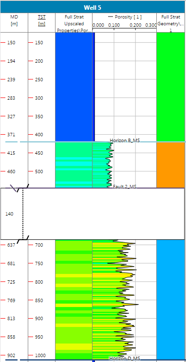
Gap in wellbore section. click to enlarge
Section overlaps
When an overlapping section occurs for a particular wellbore it is represented in the view by multiple tracks positioned next to one another, slightly offset, as if representing two separate wellbores. The wellbore name will still be displayed in the track header, however, so you can easily identify tracks that are being displayed in this manner.
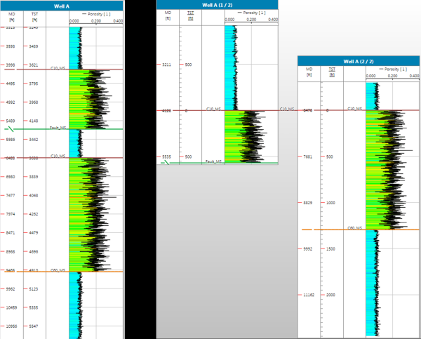
The left track displays the wellbore using a TVDSS projection, while the right two tracks display the same wellbore in TST mode. The split in the wellbore resulting from fault overlap is visible when in TST or TVT mode. It is important to note that the depth increases for both wellbore tracks in the downward direction. click to enlarge
Inflection points
Wellbores that contain inflection points are displayed in reverse of the original wellbore direction, after the inflection, so that you can better observe what the wellbore encountered as it was being drilled. For each inflection point calculated for the wellbore a new track will be created. This means that a wellbore with three inflection points will result in four different tracks in the view. Arrows at the top left corner of each of the split wellbore headers indicate the depth direction of the wellbore.
Inflection points can be imported via the standard Markers import form
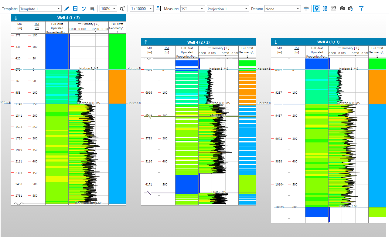
Inflection points are visible in TST and TVT mode and are indicated by a split wellbore track, similar to fault overlap displays. The distinguishing feature of inflection points, however, is that the depth direction will switch for each split wellbore section where an inflection point occurs. The change in depth direction is indicated by the arrows in the well headers. click to enlarge